IK10 vs IK09 Displays: Designing Impact-Resistant Industrial Touch Screens
Introduction
In industrial and public-facing environments, display durability is not a secondary concern—it is a core design requirement. Whether installed on a factory floor, integrated into an EV charging station, or mounted in a public kiosk, displays are constantly exposed to mechanical stress. This includes accidental impacts, tool collisions, and in some cases, deliberate damage.
To quantify and standardize impact resistance, engineers rely on IK ratings defined under the IEC 62262 standard. Among these, IK09 and IK10 are the most commonly specified levels for industrial displays.
While both provide strong protection, the difference between them is not trivial. Moving from IK09 to IK10 typically involves changes not only in glass thickness, but also in bonding methods, structural support, and touch system design.
This article looks at IK ratings from an engineering perspective—how they are defined, what actually affects them in real products, and how to approach the design of an IK10-rated display system.
Understanding IK Ratings in Practice
The IK rating system defines how much mechanical impact an enclosure can withstand. Each level corresponds to a specific impact energy, measured in joules.
In testing, this energy is applied using a standardized striker, simulating real-world impacts such as dropped tools or physical force applied to the screen.
Below is a simplified reference:
- IK06: 1 joule, light indoor equipment
- IK07: 2 joules, basic industrial environments
- IK08: 5 joules, semi-outdoor installations
- IK09: 10 joules, public terminals and charging stations
- IK10: 20 joules, vandal-resistant and heavy-duty outdoor systems
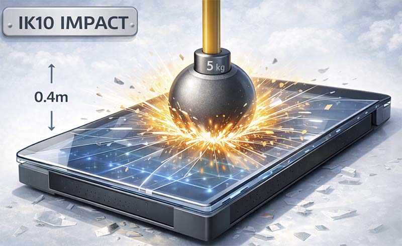
At IK10 level, the display must survive impacts equivalent to a 5 kg object striking from a height of 40 cm. This is not a theoretical scenario—it reflects real risks in public and industrial environments.
Why IK Ratings Matter for Industrial Displays
In controlled lab conditions, most displays perform well. However, real-world environments introduce unpredictable mechanical stress.
Typical risk scenarios include:
- Tools accidentally hitting the screen during maintenance
- Equipment vibration leading to repeated minor impacts
- Public misuse or vandalism in unattended installations
- Environmental factors such as debris or falling objects
Without sufficient protection, these factors can lead to cracked glass, touch failure, or complete system downtime.
For industrial systems, downtime is often more costly than the display itself. This is why selecting the correct IK rating is not just about protection—it is about system reliability.
IK09 vs IK10: What Actually Changes
At a glance, IK09 (10J) and IK10 (20J) differ only in impact energy. In practice, achieving IK10 requires a significantly stronger design.
The transition from IK09 to IK10 typically involves:
- Thicker or stronger cover glass
- Improved bonding between layers
- Reinforced mechanical housing
- Enhanced edge support
The difference is especially noticeable in large-format displays, where the center area becomes more vulnerable to impact.
In many designs, IK09 can be achieved with moderate reinforcement, while IK10 often requires a fully optimized mechanical and optical stack.
Glass Thickness and Impact Resistance
One of the most visible factors in IK-rated design is cover glass thickness. Thicker glass helps distribute impact energy across a larger area, reducing localized stress.
A typical reference range looks like this:
- 2.0 mm: around IK06
- 3.0 mm: around IK07
- 4.0 mm: around IK08
- 5.0 mm: around IK09
- 6.0 mm and above: approaching IK10
However, thickness alone does not guarantee performance. Material quality, edge finishing, and mounting conditions all influence the final result.
Tempered glass is commonly used due to its improved strength and safety characteristics. In some cases, chemically strengthened glass is used to further enhance resistance.
The Trade-Off: Glass Thickness vs Touch Performance
Increasing glass thickness introduces a secondary challenge—touch sensitivity.
Capacitive touch systems rely on detecting changes in an electric field. As the glass layer becomes thicker, the signal from the user’s finger must travel through a larger dielectric distance. This reduces signal strength and can affect responsiveness.
To compensate for this, engineers typically:
- Use higher-performance touch controller ICs
- Adjust drive voltage and sensing parameters
- Optimize firmware filtering algorithms
- Tune the touch system for the specific glass thickness
Designing an IK10 display with reliable touch performance is therefore not just a mechanical task—it requires coordinated electrical and firmware optimization.
Bonding Methods and Their Impact on IK Rating
The method used to bond the display layers plays a major role in impact resistance.
Air Bonding
Air bonding leaves a gap between the cover glass and the display panel. While cost-effective, this structure introduces a weak point where impact energy can concentrate.
Optical Bonding
Optical bonding fills the gap with a transparent adhesive. This creates a unified structure that distributes impact forces more evenly.
In practice, optical bonding offers several advantages:
- Increased structural rigidity
- Reduced internal reflections
- Improved durability under impact
For IK10 designs, optical bonding is often considered essential rather than optional.
Mechanical Design Considerations
Even with strong glass and proper bonding, poor mechanical design can undermine the entire system.
Key considerations include:
Edge Support
The edges of the glass are critical stress points. Proper support reduces the likelihood of cracking during impact.
Back Structure
A reinforced backplate helps distribute force across the entire module instead of concentrating it at the impact point.
Mounting Method
The way the display is fixed into the enclosure affects how energy is absorbed. Flexible mounting can reduce stress, while rigid mounting may transfer impact directly to the glass.
Display Size
Larger displays are inherently more vulnerable, especially at the center. Additional reinforcement is often required to achieve IK10 on larger panels.
Material Choices Beyond Glass
While glass is the primary protective layer, other materials can also be considered.
Polycarbonate offers high impact resistance and is less likely to shatter. However, it is more prone to scratching and may not provide the same optical clarity as glass.
In some designs, hybrid approaches are used to balance durability and visual performance.
Application Scenarios for Different IK Levels
Selecting the correct IK rating depends on the environment.
IK06–IK07
Used in indoor equipment where mechanical stress is minimal.
IK08
Suitable for semi-protected environments such as kiosks or industrial terminals with limited exposure.
IK09
Common in public infrastructure, including EV chargers and ticketing machines.
IK10
Required for:
- Outdoor HMIs
- Public-facing terminals
- High-traffic areas
- Vandal-prone installations
In these cases, impact resistance is a critical part of the product specification.
When IK10 Is the Right Choice
IK10 is not necessary for every application. However, it becomes important when:
- Devices are installed in unattended environments
- Physical interaction is frequent and unpredictable
- There is a risk of intentional damage
- Maintenance access is limited
- Long service life is required without frequent replacement
In these scenarios, the additional design effort required for IK10 is justified by improved reliability.
Designing a Custom IK10 Display
Achieving IK10 performance requires a system-level approach.
It typically involves:
- Selecting appropriate glass thickness and material
- Using optical bonding to improve structural integrity
- Designing a reinforced mechanical housing
- Ensuring proper edge and back support
- Optimizing touch performance for thicker glass
Testing is also critical. Designs should be validated under real conditions to ensure compliance with IEC 62262 requirements.
Conclusion
Impact resistance in industrial displays is not defined by a single component. It is the result of multiple design decisions working together—materials, bonding, mechanical structure, and electronics.
While increasing glass thickness is an important step, it is only part of the solution. True IK10 performance requires a coordinated design approach that balances durability, usability, and long-term reliability.
For engineers developing displays in demanding environments, understanding how these factors interact is essential. A well-designed impact-resistant display not only survives harsh conditions but also reduces maintenance costs and improves overall system stability.